


|
|
|||||||
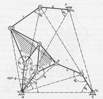
Construction of the Robert's connection for the five-membered gear |
|||||||
|---|---|---|---|---|---|---|---|
 Click to enlarge Click to enlarge
|
Description
The Figure shows the view of the gear with hinges at B and M and screw joint at Hj, H2, H3 are parallel with the slope p 1, P2 and P3 at A, C and Q. All the screw axis and rotary axis. |
||||||
| Linked items | |||||||
|
|||||||
| Permanent links | |||||||
|
|
|||||||
| Data provider | |||||||
|
|
|||||||