 Premi per ingrandire Premi per ingrandire
|
Description
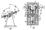
A kinematic diagram of the mechanism is shown in Fig. a and a design version of a speed gearbox based on this mechanism is shown in Fig. b. Links 1 and 2 rotate independently of each other about fixed axis A. Link 3, rotating about fixed axis B, is designed as a slotted link with two slots, c and d. Link 3 is connected by sliding pairs C and D to sliders 4 and 5 which, in turn, are connected by turning pairs to cranks 1 and 2. Cranks 2 and 1 are designed as gears meshing with pinions 6 and 7 which are rigidly mounted on shafts E and F. These shafts rotate in fixed bearings of the speed gearbox. Angles of rotation ϕ₁, ϕ₂ and ϕ₃ of links 1, 2 and 3 are related by the conditions: ϕ₁=arctan((B͞C sin(ϕ₃))/(A͞D+(B͞Cos(ϕ₃)))) ϕ₂=arctan((B͞Csin(ϕ₃))/(B͞D-(A͞D cos(ϕ₃)))).
$1010$LG,6L$
|


 GERMANY
 SPAIN
SPAIN ROMANIA
 FRANCE
 ITALY
ITALY