|
|
|||||||
ARTOBOLEVSKY SLIDING-LINK MECHANISM FOR TRACING ROULETTES OF THE CENTRODES OF TANGENT GENERATORS |
|||||||
|---|---|---|---|---|---|---|---|
Pinche para ampliar
|
Description
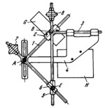
The mechanism is based on a tangent generator consisting of links 1, 2, 3 and 4. Added to this linkage is a double guiding element consisting of two sliders, 5 and 6, connected together by turning pair E. Links 1 and 3 have wheels 7 and 8 wi th sharp-edged rims, which can only rotate about their axes. The mechanism is intended for tracing the roulettes of the centrodes of links 2 and 4. For this purpose, a stylus at the centre of pivot E is placed on the curve with respect to which the roulet te of the centrode of link 2 or 4 is to be obtained. Wheels 7 and 8 are set on a plane table. When the stylus of pivot E is moved along the above-mentioned curve so that wheels 7 and 8 roll along the plane table, any point of plane members G and H, at tached respectively to links 2 and 4, describes the corresponding roulette of the centrode of link 2 or link 4. The mechanism can be set up for various centrodes by adjusting pivot A along the slot of link 4. |
||||||
| Linked items | |||||||
|
|||||||
| Permanent links | |||||||
|
|
|||||||
| Data provider | |||||||
|
|
|||||||
|
DMG-Lib Accueil + Actualités
|
Parcourir
|
Recherche
|
Essayer DMG-Lib
|
About us
|
Aide
|
|
|
|||||||
ARTOBOLEVSKY SLIDING-LINK MECHANISM FOR TRACING ROULETTES OF THE CENTRODES OF TANGENT GENERATORS |
|||||||
|---|---|---|---|---|---|---|---|
Cliquez pour agrandir
|
Description
The mechanism is based on a tangent generator consisting of links 1, 2, 3 and 4. Added to this linkage is a double guiding element consisting of two sliders, 5 and 6, connected together by turning pair E. Links 1 and 3 have wheels 7 and 8 wi th sharp-edged rims, which can only rotate about their axes. The mechanism is intended for tracing the roulettes of the centrodes of links 2 and 4. For this purpose, a stylus at the centre of pivot E is placed on the curve with respect to which the roulet te of the centrode of link 2 or 4 is to be obtained. Wheels 7 and 8 are set on a plane table. When the stylus of pivot E is moved along the above-mentioned curve so that wheels 7 and 8 roll along the plane table, any point of plane members G and H, at tached respectively to links 2 and 4, describes the corresponding roulette of the centrode of link 2 or link 4. The mechanism can be set up for various centrodes by adjusting pivot A along the slot of link 4. |
||||||
| Linked items | |||||||
|
|||||||
| Permanent links | |||||||
|
|
|||||||
| Data provider | |||||||
|
|
|||||||