


|
|
|||||||
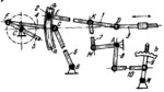
LINK-GEAR VALVE GEAR MECHANISM |
|||||||
|---|---|---|---|---|---|---|---|
 Ansicht vergrößern Ansicht vergrößern
|
Beschreibung
Connecting rod 1 is connected by turning pairs E and D to circular slider 2 and rod 3 of the valve. Slider 2 moves along circular guides a-a of link 4 which is connected by turning pairs F and G to crank 5 and link 6. Crank 5 rotates about fixed axis C and link 6 turns about fixed axis B. Link 7 is connected by turning pairs K and M to connecting rod 1 and to bent lever 8 which turns about fixed axis A. Link 8 is connected by intermediate link 10 to lever 9 which turns about fixed axis N. The stroke of valve rod 3 is varied by setting lever 8 to the proper position and fixing it by means of lever 9 which has a tooth entering one of the slots of toothed quadrant b. |
||||||
| Verknüpfte Datensätze | |||||||
|
|||||||
| Permanentlinks | |||||||
|
|
|||||||
| Datenbereitsteller | |||||||
|
|
|||||||