 Ansicht vergrößern Ansicht vergrößern
|
Beschreibung
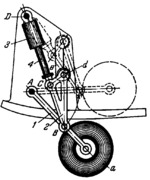
Link 1 with wheel a turns about fixed axis A of the aircraft frame member. Link 2 is connected by turning pairs B and C to links 1 and piston rod 4 of retracting cylinder 3. Cylinder 3 turns about fixed axis D of the aircraft frame. Link 2 has roller d which slides freely along slot e of the aircraft frame. When piston rod 4 moves into retracting cylinder 3, link 1 turns counterclockwise, and the landing gear is retracted as shown by the dash lines. At the extreme positions of link 2, its roller d enters notches of slot e thereby relieving the load on the retracting cylinder.
$1441$LG,AL$
|


