 Ansicht vergrößern Ansicht vergrößern
|
Beschreibung
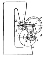
Designed as a disk, crank 1 rotates about fixed axis A and is connected by turning pairs B to connecting rod 5 and gear 4. Connecting rod 5 is connected by turning pair C to rocker arm 6 which turns about fixed axis D. Gear 4 meshes with gear 2 which rotates about axis C. Gear 2 meshes with gear 3 which is rigidly attached to the base. When crank 1 rotates, gears 2 and 4 have complex motions. The transmission ratios from crank 1 to gears 2 and 4 equal i₁₂=ω₁/ω₂=i₁₆/(1-i₂₃)=i₁₆z₂/(z₂+z₃) and i₁₄=ω₁/ω₄=i₁₅/(1-i₄₂)=i₁₅z₂/(z₂+z₄) where ω₁,ω₂ and ω₄ are the angular velocities of crank 1 and gears 2 and 4, and z₂, z₃ and z₄ are the numbers of teeth of gears 2, 3 and 4. The transmission ratios i₁₅=ω₁/ω₅ and i₁₆=ω₁/ω₆, where ω₁, ω₅ and ω₆ are the angular velocities of links 1, 5 and 6, are determined on the basis of the given dimensions of crank and rocker-arm linkage ABCD.
$2455$LrG,ML$
|


