 Ansicht vergrößern Ansicht vergrößern
|
Beschreibung
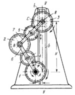
Gear 1 rotates about fixed axis A. Crank 6 rotates about axis A independently of gear 1. Gear 1 meshes with gear 4 which rotates about axis D of crank 6 and meshes, in turn, with gear 2. Gear 2 rotates about axis B and meshes with gear 5 which rotates about axis E of connecting rod 7 and meshes, in turn, with gear 3. Connecting rod 7 is connected by turning pairs B and C to crank 6 and to gear 3 and slider 8. Slider 8 moves along fixed guides b-b. Since gears 1, 2 and 3 have the same dimensions, as do gears 4 and 5, the length of crank 6 equals that of connecting rod 7. When driving gear 1 rotates with angular velocity ω₁ and driving crank 6 rotates with angular velocity ω₆, independent of ω₁, driven gear 3 rotates about axis C with angular velocity ω₁ and reciprocates along axis y-y. The displacement of gear 3 is y=l(sin(ϕ)±sqrt(1-(x-cos(ϕ))²)) where l is the length of links 6 and 7, x=a/l and ϕ is the angle of rotation of crank 6. If a=0, then the displacement y=2l sin(ϕ). Different kinds of motion of driven gear 3 can be obtained by varying the magnitudes and directions of angular velocities ω₁ and ω₆.
$2456$LrG,ML$
|


