


|
|
|||||||
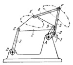
SIX-BAR MECHANISM |
|||||||
|---|---|---|---|---|---|---|---|
 Click to enlarge Click to enlarge
|
Description
Links 5 and 4 are connected by turning pairs G and E to bell crank 1 and connecting rod 2 of four-bar linkage ABCD. Points of links 2, 4 and 5 describe complex connecting-rod curves whose shape depends upon the sizes of the links of the mechanism. Thus, for example, upon rotation of crank 1, points E and F of link 4 describe the connecting-rod curves shown in the drawing. |
||||||
| Linked items | |||||||
|
|||||||
| Permanent links | |||||||
|
|
|||||||
| Datenbereitsteller | |||||||
|
|
|||||||