Structure of mechanism |
| Function |
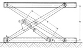
Bild 2.1/7 zeigt eine Hebebühne, deren obere Platform durch einen Hydraulikzylinder zwischen den Drehgelenken E0 und E gehoben und gesenkt werden kann.
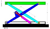
Das kinematische Schema der Hebebühne (Bild 2.1/8) zeigt ein sechsgliedriges Getriebe mit fünf Drehgelenken (A0, E0, A, E, C), einem Schubgelenk zwischen Hydraulikkolben und -zylinder (Glieder 4 und 5) und zwei Gleitdrehgelenken. Ersetzt man die Gleitdrehgelenke durch Gleitsteine mit Dreh- und Schubgelenken, erhält man das hier beschriebene äquivalente achtgliedrige Kurbelgetriebe mit Dreh und Schubgelenken. |
| Dimension of mechanism |
planar |
| Number of links |
8 |
| Drive movement |
Rectilinear translation |
| Output movement |
Frame motion |
| Degree of freedom |
1 |
| Fundamental mechanism |
 Link containing mechanism Link containing mechanism
 Mechanism, containing pressurizing medium Mechanism, containing pressurizing medium |
| Number of inputs |
1 |
| Number of followers |
1 |
| Revolution ability |
no |
| Revolution ability of input link |
no |
| Relative position between drive and output |
parallel |
| |
Guidance function |
| Direction of the path |
identical direction |
| Orientation of output link |
parallel |
| Trace of a dedicated point on follower |
 Open trace Open trace |
| Dimension of mechanism |
planar |
| Input reference |
possible |
| Progress of orientation respecting output link |
miscellaneous |
| |
Application |
| Application area |
Academic use and Other fields |
| Examples of application |
Hebebühne |
| |


 Animations
 Images
 Start interactive animation