


|
|
|||||||
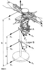
Main rotor shaft of a helicopter |
|||||||
|---|---|---|---|---|---|---|---|
 Click to enlarge Click to enlarge
|
Description
The figure shows an outline of the main rotor shaft of a helicopter. Due to imbalances in the rotor head in the angular velocity Q acting radial forces FA and FB from both bearings A and B on the wave. Their orientation in the fixed-rotor coordinate systems XA, YA and XB, YB is given by the angles a and ß. |
||||||
| Linked items | |||||||
|
|||||||
| Permanent links | |||||||
|
|
|||||||
| Data provider | |||||||
|
|
|||||||