 Pinche para ampliar Pinche para ampliar
|
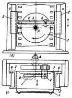
Description
Crank 1 (Fig. a) is designed as a disk rotating about fixed axis A. Pin B enters slot b of link 2 which slides along fixed guides a-a. Link 3 moves along guides of link 2 in a direction perpendicular to the motion of link 2, as shown in Fig. b. The motion of link 3 in this direction is accomplished by means of pin 4 which simultaneously enters slots b and c of links 2 and 3. When crank 1 rotates, slotted link 2 and link 3 reciprocate together in the vertical direction. Pin 4, moving along slots b and c, periodically retracts link 3, withdrawing the claws from engagement with film 1.
$1382$LG,OC$
|


