 Pinche para ampliar Pinche para ampliar
|
Description
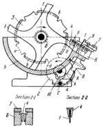
Link 2 rotates about fixed axis A and its gear segment a meshes intermittently with gear segments b of gear 3 which rotates about fixed axis B. Link 2 has concentric locking surface d which engages the corresponding concave locking surface e of gear 3 to prevent its unintentional rotation during its idle periods. Gear 3 turns through an angle of 90° to each revolution of link 2. Four-bladed member 1 is rigidly attached to gear 3. As member 1 rotates clockwise, some of the parts to be fed (split rivets 4 in the version shown), placed in hopper 5, straddle blades f, as shown in cross section II-II. As member 1 continues to turn, split rivets 4 slide along the curved edge of blade f until they reach the position shown at the tip of the blade. Each blade f dwells in this position to enable the rivets to slide off and into chute 6. In chute 6 the rivets are supported under their heads (see cross section I-I) and strips 7 are provided to prevent them from pilling up in the inclined chute. Sliding finger 8 keeps the top of chute 6 clear of incorrectly delivered rivets 4. Finger 8 is actuated by lever 9 which turns about fixed axis C and has lug k. Lug k is actuated by cam 10 which is rigidly attached to link 2. A spring pulls lever 9 toward the hopper while the motion in the other direction is from cam 10.
$2653$PG,SF$
|


