 Pinche para ampliar Pinche para ampliar
|
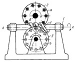
Description
Worm 1 rotates about fixed axis A-A and its threads mesh with pins a and b of pin wheels 2 and 3 which rotate about fixed axes B and C. Pins a and b are designed as rollers located on the end faces of wheels 2 and 3, and can rotate about their axes, thereby substantially reducing friction losses in the gearing. Axes B and C are parallel to each other and are perpendicular to, but do not intersect, axis A-A. The transmission ratios of the mechanism are i₁₂=ω₁/ω₂=z₂/z₁ and i₁₃=ω₁/ω₃=z₃/z₁ where ω₁, ω₂ and ω₃ are the angular velocities of worm 1 and of pin wheels 2 and 3, z₁ is the number of threads (starts) on worm 1, and z₂ and z₃ are the numbers of pins a and b on wheels 2 and 3. When driving worm 1 rotates, pin wheels 2 and 3 rotate in opposite directions.
$2815$WG,4L$
|


