 Pinche para ampliar Pinche para ampliar
|
Description
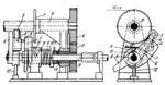
Rotation is transmitted from shaft A to shaft B as follows. Clutch member 1, shrink-fitted on shaft A, engages the clutch teeth of sleeve 14 on which gear 3 is keyed. Gear 3 meshes with gear 4 which is keyed on shaft B. Secured on shaft B is reel 2 on which wire is being wound. As wire reel 2 becomes filled and due to its increasing diameter, roll 5, resting on the layers of wire, is gradually forced outward so that its lever 6 is turned clockwise. At this, slot a of lever 6 pushes pin b with latch 7 upwards with respect to its fixed guide. As soon as latch 7 is disengaged from hand-lever 8, secured to sleeve 9, the lever and sleeve begin to turn clockwise by the action of torsion spring 10. Since sleeve 9 has helical cam slot e, it is shifted to the left when turned clockwise. This disengages clutch members 1 and 14 and shaft B stops. After the full reel is removed and replaced by an empty one, hand-lever 8 is turned downward (counterclockwise). This advances roll 5 to the core of the reel so that slot a allows pin b to move downward and latch 7 again engages the projection of hand-lever 8, locking the lever in position. The downward movement of hand-lever 8 also turns sleeve 9 which, due to the reverse action of pin 11 in cam slot e, is shifted to the right re-engaging clutch members 1 and 14 so that rotation is again transmitted to reel 2. Roll 5 is held in contact with the layers of wire by a weight pulling cable 13 to the left. Lever 6 turns freely on drive shaft A and is prevented from moving axially by fixed pin 12.
$1725$LC,SD$
|


