 Pinche para ampliar Pinche para ampliar
|
Description
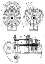
When cylinder cam 1, whose end view is shown, rotates about fixed axis B, it imparts intermittent rotation to shaft 9 about fixed axis E and oscillation to shaft 10, synchronous to the motion of shaft 9. Disks 2, keyed to shaft 9, rotate intermittently, and workpieces 3, resting In the U-shaped grooves of sliders 4, are fed to the laying-out station. From considerations of design it is necessary for workpieces 3 to follow path a. For this purpose, rollers 5, mounted on sliders 4, roll and slide along profiled grooves d of fixed disks 6. As soon as workpiece 3 reaches position 3’, centre-punches 7 begin to move inward by the action of profiled grooves b on their holders. When the workpiece reaches position 3”, it is centre-punched. After this, disk 8, keyed to shaft 10, turns in the opposite direction to retract centre-punches 7 and, after reversal of disk 8, they are advanced radially again to centre-punch the next workpiece. Thus, disks 2 periodically feed workpieces 3 to be centre-punched.
$3240$CmL,SF$
|


