 Cliquez pour agrandir Cliquez pour agrandir
|
Description
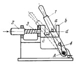
Lever 1, turning about fixed axis A, has pin a and is subject to the action of flat spring 4. Link 2 has slotted component b, of complex shape, at one end. Component b has two flat surfaces, d and c, arranged at different levels. When engaged, lever 1 is in the position shown in the drawing, i .e. where pin a rests on surface d . When link 2 is pushed toward the right, lever 1 is returned by spring 4 to the initial position (shown by dash lines), i.e. where pin a rests on surface c. Spring 3 returns link 2 to its initial position when lever 1 is turned clockwise.
$153$SL,L$
|


