 Cliquez pour agrandir Cliquez pour agrandir
|
Description
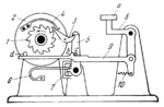
Continuously rotating ratchet wheel 1 has a common axis with driven disk 2. Pawl 3, pivoted on disk 2, is actuated by spring 4. Engagement of pawl 3 and ratchet wheel 1 is prevented by stop lever 5, held by spring 6 against stop 7. When key a of two-armed lever 8 is depressed, start ing rod 9, hinged to lever 8, is moved to the right. Shoulder b of rod 9 turns lever 5 to free pawl 3 which engages ratchet wheel 1. At this, disk 2 begins to rotate. Pin d, pressing downward on the left end of rod 9, disengages it from lever 5 which returns to its initial position and catches pawl 3 after one revolution of disk 2. When key a is released, rod 9 is returned by spring 10 to its horizontal position and moves to the left so that shoulder b, which was to the right of pin c, returns to the position shown in the drawing.
$484$SL,K$
|


