 Cliquez pour agrandir Cliquez pour agrandir
|
Description
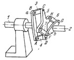
The lengths of the links comp ly with the conditions: A͞B=D͞C, B͞C=A͞D, E͞H=F͞G and E͞F=H͞G. Cross-piece a is secured rigidly to shaft 1 and cross-piece b to shaft 2 whose axis does not coincide with, but is parallel to, the axis of shaft 1. Cross-type connecting rod 5 is connected by turning pairs C, D, H and E to cranks 3, 4, 6 and 7. Rotation is transmitted from shaft 1 to shaft 2 through two parallel-crank linkages ABCD and EFGH which have a common cross-type connecting rod 5.
$801$LW,C$
|


