 Cliquez pour agrandir Cliquez pour agrandir
|
Description
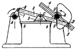
Slider 5 of crank-and-slider linkage ABC moves along guides b-b. Point D of connecting rod 2 describes a path of which portion y-y, shown by a heavy continuous line, approximates a straight line perpendicular to guides b-b. When crank 1 rotates about fixed axis A, link 2, connected by turning pair D to slider 3, imparts oscillating motion with dwells to slotted link 4. The dwell of link 4 corresponds to the travel of point D of slider 3 along portion y-y of its path. Groove a of the upright, along which slider 3 travels when linkage ABC is in an extreme (dead centre) position, prevents accidental rotation of link 4 during the dwell period.
$1349$LG,D$
|


 Newsletter
 DMG-Lib
 Europeana
 Ilmenau TU