 Cliquez pour agrandir Cliquez pour agrandir
|
Description
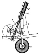
Link 5 turns about fixed axis D of the aircraft frame member. Link 1 with wheel a is connected by turning pair A to link 5. Piston rod 4 of retracting cylinder 2 is connected by turning pair B to link 1. Cylinder 2 turns about fixed axis C of the aircraft frame. When piston rod 4 moves into retracting cylinder 2, link 1 is turned clockwise about axis A, and the landing gear is retracted as shown by the dash lines. Shock absorber 3 is mounted between points A and C.
$1430$LG,AL$
|


