


|
|
|||||||
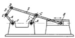
SLIDER-CRANK MECHANISM WITH AN ATTACHED DOUBLE GUIDING ELEMENT |
|||||||
|---|---|---|---|---|---|---|---|
 Cliquez pour agrandir Cliquez pour agrandir
|
Description
Link 3 is attached through turning pair D to connecting rod 2 of slider-crank linkage ABC. Link 3 is connected by turning pair E to link 4 which turns about fixed axis F. When crank 1 rotates about fixed axis A, point D of connecting rod 2 describes a connecting-rod curve. Depending upon the lengths of links 2, 3 and 4, link 4 either makes complete revolutions about axis F or oscillates about this axis. |
||||||
| Linked items | |||||||
|
|||||||
| Permanent links | |||||||
|
|
|||||||
| Data provider | |||||||
|
|
|||||||