 Cliquez pour agrandir Cliquez pour agrandir
|
Description
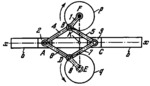
The lengths of the links comply with the conditions: A͞B=B͞C=C͞D=D͞A and F͞K=K͞F. Figure ABCD is a rhombus linkage. Link 1 rotates about fixed axis F and is connected by turning pairs B to links 4 and 5. Links 4 and 6, and 5 and 7 are connected by turning pairs A and C to sliders 2 and 3 which move along guides b-b. When link 1 rotates about axis F, point B describes circle p of radius F͞B, and point D describes circle q of radius E͞D=F͞B. Point E lies on straight line FKE, perpendicular to axis x-x of guides b-b. Therefore, if we add link 8 shown by dash lines, the mechanism has a constant transmission ratio between links 1 and 8 equal to i₁₈=ω₁/ω₈=-1. Links 6, 7 and 8 are the mirror images of links 4, 5 and 1 with respect to axis x-x. Links 1 and 8 rotate in opposite directions.
$1557$SC,GI$
|


