 Cliquez pour agrandir Cliquez pour agrandir
|
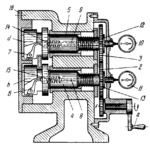
Description
When crank handle a is rotated, motion is transmitted to bars 4 and 5 through meshing gears 1, 2 and 3. Disks band d at the left-hand ends of bars 4 and 5 have slots in which levers 6 and 7 are mounted. If the dimensions in the bores of gearbox cover 16 deviate from the required values, levers 6 and 7 transmit the deviation through pins 8 and 9, passing through holes in the bars, to the contact points of dial indicators 11 and 10. Springs 12, 13, 14 and 15 hold the contact points of levers 7 and 6 against the surfaces being checked.
$2549$LrG,FD$
|


