 Cliquez pour agrandir Cliquez pour agrandir
|
Description
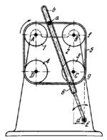
The lengths of the links comply with the conditions: r₁=r₂=r₃=r₄ where r₁, r₂, r₃ and r₄ are the radii of pulleys 1, 2, 3 and 4; A͞B=B͞C=C͞D=D͞A; and the distance between point E and line BC is d=r₁. Figure ABCD is a square. Pulley 1 rotates about fixed axis A and, through flexible link 5, rotates pulleys 2, 3 and 4 about fixed axes B, C and D. Pin a of flexible link 5 slides along slot b of slotted link 6 which turns about fixed axis E. When pulley 1 rotates about axis A, slotted link 6 oscillates about axis E. When pin a travels along straight portion fg of its path, slotted link 6 has a dwell in its right-hand extreme position.
$1934$FL,D$
|


