


|
|
|||||||
LEVER-CAM GRIP |
|||||||
|---|---|---|---|---|---|---|---|
 Cliquez pour agrandir Cliquez pour agrandir
|
Description
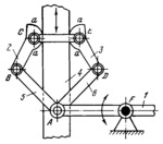
Links 2 and 3 are designed as cams with working surfaces a-a. The lengths of the links comply with the conditions: A͞B=A͞D and B͞C=D͞E. When link 1 is turned clockwise about fixed axis F, cams 2 and 3 grip plate 4 and advance it. When link 1 is turned in the reverse direction, plate 4 is released. |
||||||
| Linked items | |||||||
|
|||||||
| Permanent links | |||||||
|
|
|||||||
| Data provider | |||||||
|
|
|||||||