 Cliquez pour agrandir Cliquez pour agrandir
|
Description
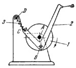
Link 1 rotates about fixed axis A and is connected by turning pair B to connecting rod 2, designed as a bent lever. Spring 3 is connected by turning pairs C and D to connecting rod 2 and to the base. When crank 1 rotates, the tip of claw a of connecting rod 2 describes a connecting-rod curve. At one portion of this curve, claw a is inserted into a perforation of the film, advances the film and is withdrawn The required shape of the path of claw a is obtained by properly selecting the dimensions of spring 3.
$2125$EL,OC$
|


