 Cliquez pour agrandir Cliquez pour agrandir
|
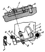
Description
Slider 1 reciprocates. At the initial instant of motion of slider 1 in the direction of the arrow, pin a of the slider, in slot d of lever 2, turns lever 2 clockwise together with lever 3 about fixed axis A. At this, the left end of lever 3, designed as a cam, actuates roll e of index pin 4, withdrawing the pin from its seat in the table (not shown). Before roll e runs off surface b of the cam, the table is swivelled by slider 1 through the required angle. Upon further motion of slider 1, slot d of lever 2 becomes parallel to the line of motion of slider 1 and index pin 4 remains in the withdrawn position. In the reverse stroke of slider 1, lever 2 is turned counterclockwise and lever 3, overcoming the resistance of spring 5, turns about axis B so that roll e moves along surface f of the cam, inserting index pin 4 into the next seat of the table. As soon as the end of lever 3 passes over roll e, the lever is returned by spring 5 to the position shown.
$1729$LC,FD$
|


