 Cliquez pour agrandir Cliquez pour agrandir
|
Description
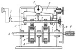
Bar 2, being tested, is mounted in bearings 3 and is fitted in to spherical members a. Driving shaft 1 rotates about fixed axis A and carries holders 4 with rollers b which act on members a. As each pair of rollers b passes under bar 2, the latter is bent upward. Bearings 3 can be adjusted vertically by wedge 5. Instrument 6 indicates the bending deflection of bar 2. Electrical device 7 indicates the instant of contact between bar 2 and instrument 6. Pin wheel 8 turns bar 2 through 90° between consecutive blows. Counter 9 indicates the number of revolutions bar 2 makes up to its failure.
$3445$CF,M$
|


