


|
|
|||||||
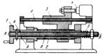
SIDE CAM AND SCREW DISENGAGING MECHANISM |
|||||||
|---|---|---|---|---|---|---|---|
 Cliquez pour agrandir Cliquez pour agrandir
|
Description
When handwheel 1 is rotated about fixed axis A-A, screw 2 traverses slide 3, whose lower end is a nut, along fixed guide d. As soon as slide 3 runs up against stop 4, or the mechanism is overloaded, cam surface a of handwheel 1, designed as an inclined plane, begins to turn with respect to mating cam surface b of screw 2. This shifts shaft 6 to the left, compressing spring 5 and screw 2 remains stationary. |
||||||
| Linked items | |||||||
|
|||||||
| Permanent links | |||||||
|
|
|||||||
| Data provider | |||||||
|
|
|||||||