 Premi per ingrandire Premi per ingrandire
|
Description
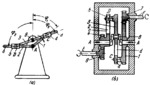
A kinematic diagram of the mechanism is shown in Fig. a and a design version of a speed gearbox based on this mechanism is shown in Fig. b. Links 1 and 2 rotate independently of each other about fixed axis A. Link 3, rotating about fixed axis B, is designed as a two-arm lever connected by turning pair D to slider 5 and by sliding pair C to slider 4. Slider 5 moves along slot c of link 2, and slider 4 moves along slot d of link 3. Link 2 is rigidly attached to gear e and link 1 is designed as a gear. Gears e and 1 mesh wi th pinions 6 and 7 which are rigidly mounted on shafts E and F. These shafts rotate in fixed bearings of the speed gearbox. Angles of rotat ion q>i, f 2 and <p3 of links 1, 2 and 3 are related by the conditions: ϕ₃=arctan((A͞C sin(ϕ₁))/((A͞C cos(ϕ₁))-A͞B)=arctan((A͞D sin(ϕ₂))/(A͞B-(A͞Dcos(ϕ₂))))
$1012$LG,6L$
|


