 Premi per ingrandire Premi per ingrandire
|
Description
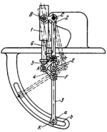
Bent lever 2 turns about fixed axis C. Cylinder 1 is connected by turning pair B to lever 2. Rod 6 of the piston sliding in cylinder 1 is connected by turning pair A to links 4 and 5. Links 5 and 4 are connected by turning pairs D and F to lever 2 and link 3. Link 3 is connected by turning pair E to lever 2 and has pin a at point K which slides along fixed circular slot b. When piston 6 moves into cylinder 1, the distance between axes A and B is reduced, and links 2, 3, 4 and 5 take the positions shown by the dash lines. In the working position of the brace, points C, D, E, F and K are on a straight line.
$1042$LG,ML$
|


