


|
|
|||||||
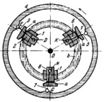
LINK-GEAR BRAKE MECHANISM |
|||||||
|---|---|---|---|---|---|---|---|
 Premi per ingrandire Premi per ingrandire
|
Description
Links 3, 5 and 7 are connected by turning pairs E, F and G to housing 4 which rotates about fixed axis 0. Pins 2, 6 and 8, with braking members a, are connected by sliding pairs to guides 1 which rotate together with housing 4. Pins 2, 6 and 8 are connected by turning pairs D, K and N to links 3, 5 and 7. When housing 4 is turned counterclockwise with respect to guides 1, members a are pressed against fixed body b, thereby braking the housing. |
||||||
| Linked items | |||||||
|
|||||||
| Permanent links | |||||||
|
|
|||||||
| Data provider | |||||||
|
|
|||||||