 Premi per ingrandire Premi per ingrandire
|
Description
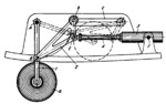
Link 1 with wheel a turns about fixed axis A of the aircraft frame member. Link 2 is connected by turning pairs B and E to link 1 and piston rod 4 of retracting cylinder 3. Cylinder 3 turns about fixed axis F of the aircraft frame. Link 2 has roller b which slides freely along slot c of the aircraft frame. When piston rod 4 moves into retracting cylinder 3, link 1 is turned counterclockwise, and the landing gear is retracted as shown by the dash lines. When the landing gear is lowered, roller b of link 2 enters a notch of slot c so that link 2 serves as a brace for link 1. This relieves the load on cylinder 3. When the landing gear is retracted, roller b automatically comes out of the notch and slides along slot c.
$1431$LG,AL$
|


