


|
|
|||||||
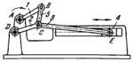
SIX-BAR SLIDER-CRANK MECHANISM |
|||||||
|---|---|---|---|---|---|---|---|
 Premi per ingrandire Premi per ingrandire
|
Description
Connecting rod 3 is attached by turning pair C to four-bar linkage ABCD and is connected by turning pair E to slider 4. The lengths of the links comply with the conditions A͞B+A͞D<B͞C+D͞C, so that links 1 and 2 are both cranks. When crank 1 rotates about fixed axis A at uniform velocity, crank 2 rotates about fixed axis D at nonuniform velocity, and the times for the forward and return strokes of slider 4 differ. |
||||||
| Linked items | |||||||
|
|||||||
| Permanent links | |||||||
|
|
|||||||
| Data provider | |||||||
|
|
|||||||