 Premi per ingrandire Premi per ingrandire
|
Description
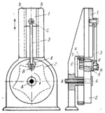
Disk 2 rotates about fixed axis A-A and is connected by turning pair E to link 4 which is designed as crank d. The crankpin of link 4 is cpnnected by turning pair B to connecting rod 3 which, in turn, is connected by turning pair C to slider 1. Slider 1 travels along fixed guides b-b. Pinion a is rigidly attached to link 4 and meshes with fixed internal gear 5, in which it rolls. When disk 2 rotates, pinion a rolls around in gear 5 and thereby imparts supplementary rotation to crank d about axis E of link 4. If the dimensions of pinion a and gear 5 are properly chosen, axis B of crank d describes the path shown by the dash line. Reciprocating motion with dwells is imparted to slider 1. As shown, slider 1 has a dwell in its extreme upper position.
$2508$LrG,D$
|


