 Premi per ingrandire Premi per ingrandire
|
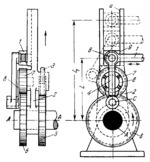
Description
Slider 9 moves along slot a of lever 2 which turns about fixed axis A. Slider 9 is connected by turning pair B to rod 1. Link 4 is connected by turning pairs B and C to slider 9 and lever 8 which is rigidly attached to pinion 7. Pinion 7 meshes with gear 6. Lever 2 carries pawl 3, shown schematically, engaging ratchet wheel 5, which is rigidly attached to gear 6, both being keyed on shaft A. When rod 1 moves to the left, pawl 3 turns ratchet wheel 5 and the whole assembly counterclockwise. On the return stroke of rod 1, pawl 3 slides over the teeth of ratchet wheel 5 while shaft A with gear 6 remain stationary. This causes pinion 7 to revolve about gear 6, turning lever 8 to the position shown by dash lines. At this link 4 pushes slider 9 upward, increasing the distance A͞B. Thus the length of the lever arm is varied from L to L₁, increasing and decreasing the amplitude of oscillation of lever 2 and thereby varying the angular velocity of ratchet wheel 5 and gear 6. The number of cycles of velocity variation per revolution of gear 6 depends on the gearing ratio between gears 6 and 7.
$1833$LR,ML$
|


