 Premi per ingrandire Premi per ingrandire
|
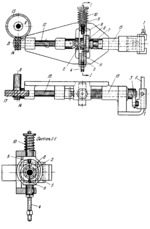
Description
Helical gear 13 rotates about fixed axis A and meshes with helical gear 14 which is keyed to shaft 12 and rotates about fixed axis B. When shaft 12 rotates continuously, an intermittent reciprocating motion with dwells at the ends of each stroke is transmitted to slide 1 through shaft 15 and crank 3, due to the periodical engagement and disengagement of clutch 2. The clutch is engaged by a clock mechanism (not shown). When rod 4 of yoke 5 is pulled downward by the action of the clock mechanism, cam 6 together with the right-hand member of clutch 2 is shifted by spring 7 along feather keys on shaft 15, thereby engaging the right- and left-hand members of clutch 2 so that shaft 15 begins to rotate. As it turns, cam 6 releases upper pin 8 which drops down under the action of compressed spring 9 and makes contact with the cam contour, forcing back the right-hand member and disengaging clutch 2 so that shaft 15 stops after turning 180°. When the clock mechanism releases rod 4, yoke 5 is raised by spring 10 and, before pin 8 moves out of contact with cam 6, it is engaged by lower pin 11 which returns to its initial position in which clutch 2 is disengaged. Thus, shaft 15 turns intermittently, through 180° each time, and slide 1 reciprocates along fixed guide f with dwells at the ends of each stroke.
$3319$GrC,D$
|


