


|
|
|||||||
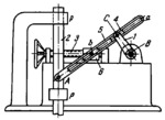
LINR-GEAR MECHANISM WITH DRIVEN LINK STROKE ADJUSTMENT |
|||||||
|---|---|---|---|---|---|---|---|
 Click pentru a mări Click pentru a mări
|
Description
Crank 1, rotating about fixed axis B, is connected by turning pair C to slider 4 which moves along slot a of slotted link 5 . Link 5 is connected by turning pair A to slider 2 which moves in fixed guides p-p. Slot a of slotted link 5 slides along pin b which belongs to slider 6. When crank 1 rotates, link 2 reciprocates. The stroke of link 2 can be adjusted by turning screw 3 to change the position of slider 6. Adjustment can be made in operation. |
||||||
| Linked items | |||||||
|
|||||||
| Permanent links | |||||||
|
|
|||||||
| Data provider | |||||||
|
|
|||||||