 Click pentru a mări Click pentru a mări
|
Description
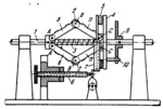
The lengths of the links comply with the condition: A͞B=B͞C. Links 8 turn about axes A of shaft 1. Connecting rods 11 are connected by turning pairs C to brake disk 4 which slides along the axis of shaft 1. When shaft 1 rotates, weights 2 are moved outward by centrifugal force and, overcoming the resistance of spring 3, force brake disk 4 against a ring with brushes 5. This ring can be adjusted axially by screw 6 and fork-shaped brushholder 7. Disk 9 and pin 10 are provided to avoid bending and torsion loads on links 8 on which weights 2 are mounted.
$1637$SC,G$
|


