 Click pentru a mări Click pentru a mări
|
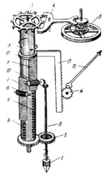
Description
Point 1 is held firmly in contact with the shaft whose speed is to be determined, and its rotation is transmitted from shaft B to s aft A through the friction spring clutch enclosed in gear 2. The angular velocity of shaft A is maintained constant by means of clockwork consisting of escape wheel 3, anchor 4 and balance wheel 5. If the shaft being tested runs at a different speed than the one corresponding to the constant speed of shaft A, the friction clutch in gear 2 begins to slip so that the constant speed of shaft A is independent of the speed of the tested shaft. Cylindrical gear racks 6 and 7 slide along shaft A and are returned to their initial position by shprings 8 and 9. Pinion 10 is driven by shaft B. Fixed pinion 11 is held to shaft A at an angle of 120° to pinion 10. During an interval corresponding to one-third revolution of shaft A, rack 6 meshes with pinion 10 and is displaced a distance proportional to the number of revolutions of shaft B (and the shaft being tested) in this interval. During the next one-third revolution, rack 6 meshes with fixed pinion 11 and consequently remains at the same height. Thus, racks 6 and 7 are alternately raised an amount proportional to the number of revolutions of shaft B in the time interval corresponding to one-third revolution of shaft A. Racks 6 and 7 raise ring 12 which carries gear rack 13. This rack rotates pinion 14 and hand 15 which indicates the average speed of the shaft being tested during one-third revolution of shaft A.
$2964$CxG,M$
|


