


|
|
|||||||
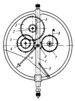
RACK-AND-PINION MECHANISM OF A DIAL INDICATOR |
|||||||
|---|---|---|---|---|---|---|---|
 Click pentru a mări Click pentru a mări
|
Description
Gear rack b, cut on indicator spindle 1, meshes with pinion 2 which is rigidly attached to a shaft together with gear 3. Gear 3 meshes with gear 4 which is rigidly attached to a shaft together with gear 5. Gear 5 meshes with pinion 6 to which hand a is rigidly attached. Backlash in the gearing and between rack b and pinion 2 is eliminated by pressure gear 7 and spiral spring 8. The contact pressure required in measurement is applied by spring 9. |
||||||
| Linked items | |||||||
|
|||||||
| Permanent links | |||||||
|
|
|||||||
| Data provider | |||||||
|
|
|||||||