 Click pentru a mări Click pentru a mări
|
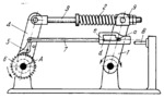
Description
Shaft A is rotated intermittently by ratchet wheel 6 and pawl 5 which is carried by lever 4. Lever 4 is oscillated by lever 1 through connecting rod 3. At the end of lever 1 is swinging yoke 9 through which rod 3 passes. Rod 3 carries spring 2 which is compressed when the load on shaft A exceeds a predetermined limit. Pawl 5 is connected to plate e by connecting rod 7. Plate e has irregular slot d and rests on pin a of lever 1. Under normal load conditions of shaft A, rod 7 carries no load, merely riding between levers 4 and 1. When shaft A is stopped by an overload, the continued motion of lever 1 to the left compresses spring 2 and pin a is carried to the wider portion of slot d so that plate e and rod 7 drop downward slightly and, when lever 1 swings to the right, pin a engages the shoulder in slot d. This pulls rod 7 to the right, disengaging pawl 5 from ratchet wheel 6 and enabling plate e to contact electric switch 8 and stop the machine. When plate e is lifted and disengaged from pin a, the machine is ready to start again if the overload on shaft A has been eliminated.
$1838$LR,SE$
|


