


|
|
|||||||
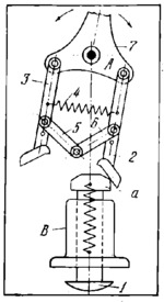
CAM-LEVER PUSH-BUTTON SWITCHING MECHANISM |
|||||||
|---|---|---|---|---|---|---|---|
 Click pentru a mări Click pentru a mări
|
Description
Push-button 1 slides in fixed guide B and has cam shoe a at its upper end. When push-button 1 is pressed, cam shoe a alternately engages pawls 2 and 3 which are connected together by links 6 and 5, and by spring 4. At this, lever 7 is switched to the corresponding position, alternately to the left and right of the vertical centre line, about fixed axis A, on successive strokes of push-button 1. |
||||||
| Linked items | |||||||
|
|||||||
| Permanent links | |||||||
|
|
|||||||
| Data provider | |||||||
|
|
|||||||