


|
|
|||||||
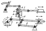
LINK-GEAR VALVE GEAR MECHANISM |
|||||||
|---|---|---|---|---|---|---|---|
 Click to enlarge Click to enlarge
|
Description
Circular slotted link 3 turns about fixed axis A. The required stroke of link 1 is obtained by setting link 3 in the proper position in which it is fixed by means of lever 2. Link 1 is reciprocated by crank-and-slider mechanism BCD through intermediate links 4, 5, 6 and 7, and slider 8 which moves along circular slotted link 3. |
||||||
| Linked items | |||||||
|
|||||||
| Permanent links | |||||||
|
|
|||||||
| Data provider | |||||||
|
|
|||||||