


|
|
|||||||
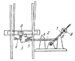
MULTIPLE-BAR MECHANISM OF A RAILWAY SWITCH |
|||||||
|---|---|---|---|---|---|---|---|
 Click to enlarge Click to enlarge
|
Description
Link 2 connects lever 1 to link 3. To set the switch, lever 1 is shifted from support B to support A. At this, link 2 turns link 3 about fixed axis 0 and tie-rods 4 and 5 operate the switch. Weight 6 locks lever 1, holding the switch in either position. Lever 1, link 2 and the base have been conditionally turned through 90° in the drawing. |
||||||
| Linked items | |||||||
|
|||||||
| Permanent links | |||||||
|
|
|||||||
| Data provider | |||||||
|
|
|||||||