


|
|
|||||||
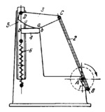
LEVER-CAM ROLLING-LEVER MECHANISM |
|||||||
|---|---|---|---|---|---|---|---|
 Click to enlarge Click to enlarge
|
Description
Crank 1 rotates about fixed axis A. Link 2 is connected by turning pairs B and C to links 1 and 3. Link 3 is designed as a cam with profile a-a. Cam 3 rolls and slides along fixed cam 4 whose profile b-b is along a straight line. Link 5 reciprocates in fixed guides. Spring 6 holds cam 3 in contact with cam 4. The law of motion of link 5 depends upon the shape of profile a-a on cam 3. |
||||||
| Linked items | |||||||
|
|||||||
| Permanent links | |||||||
|
|
|||||||
| Data provider | |||||||
|
|
|||||||