 Click to enlarge Click to enlarge
|
Description
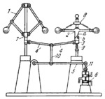
Centrifugal governor 1 reacts to changes in speed of the shaft being governed. Device 8, consisting of two balls mounted on sleeve 2, having helical cam surface a, reacts to changes in angular acceleration of the same shaft. Cam surface a contacts a corresponding projection b of sleeve 3 which is held against sleeve 2 by spring 9. Sleeves 7 and 3 are connected by tie-rods 4' and 4 of equal length. These tie-rods are connected by links 10, 5 and 11 to valve 6. The latter is connected to a servomotor (not shown) which regulates the speed of the shaft. When the speed of the shaft changes, the balls of the centrifugal governor are displaced, thereby displacing sleeve 7. At the same time, sleeve 2, due to the inertia of its balls, turns and helical cam surface a displaces sleeve 3 upward or downward, depending upon the sign of the angular acceleration.
$2248$LS,G$
|


