 Click to enlarge Click to enlarge
|
Description
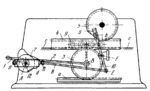
Crank 1 rotates about fixed axis A and transmits motion to gear 3 through connecting rod 2 which is connected by turning pair B to the gear. Gear 3 meshes with and rolls along fixed rack a which is secured to the foundation of the printing press. Gear 3 also meshes with the lower rack of type bed 4 which reciprocates with its rollers 9 along fixed guides c-c. A rack at the top of bed 4 meshes during the working stroke with the gear teeth of impression cylinder 5. Cylinder 5 is stationary during the idle return stroke of bed 4 and has a flat which faces downward at this time to allow the bed to pass freely under the cylinder. The cylinder is stopped and brought into engagement with the bed by fork 6 of link 10 which is actuated by main-and-return cams 7, keyed to the main shaft of the press. Fork 6 and link 10 turn about fixed axis F and are connected by turning pair E to link 8 which carries rollers 11. Slot d of link 8 slides along roller 12 which rotates about axis A. Rollers 11 roll along the two contours of main-and-return cams 7. Fork 6 catches pin b of cylinder 5, turns the cylinder to its extreme position, stops and holds it during the idle stroke of the type bed.
$3336$GrC,FD$
|


