 Click to enlarge Click to enlarge
|
Description
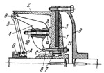
Lever 5 is connected by turning pair A to collar 6 which slides axially along one of the shafts joined by the clutch. Lever 4 is connected by turning pairs B and C to lever 5 and eyebolt 8. Eyebolt 8 passes through the hole in flanges 2 and 3 with a certain clearance. Lever 4 has projection a which slides along boss b of flange 2. When collar 6 is shifted to the left, flanges 2 and 3 are drawn together and they clamp disk 1 which is secured rigidly to flange 9. Springs 7 disengage the clutch when collar 6 is shifted to the right. The clutch is adjusted by regulating nuts 10 and 11.
$458$SL,C$
|


