 Click to enlarge Click to enlarge
|
Description
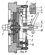
Driven friction disk 3 (dwg A) is rigidly mounted on sleeve 5 which slides freely along splines of shaft 9 of the transmission gearbox. Inside flywheel 2 is friction ring 4 which has slots b on its circumference. Projections c of flywheel 2 fit into slots b (dwg B). Due to the slots and projections, ring 4 always rotates together with flywheel 2 but can slide along its axis. Motion is transmitted from crankshaft 1 of the engine through flywheel 2, ring 4, driven disk 3 and sleeve 5 to shaft 9 of the transmission gearbox. The clutch is disengaged by a special lever mechanism. Levers 6, pivotted on brackets a of flywheel 2, have one end which enters a corresponding recess in ring 4. When clutch pedal 8 is depressed it turns shifting lever 10 of clutch sleeve 7 to the left. This also shifts ball thrust bearing d which bears against the other end of levers 6. Turning, levers 6 shift ring 4 to the right, withdrawing it from driven disk 3. The clutch is engaged by releasing pedal 8 from the action of springs 11 which squeeze disk 3 between ring 4 and flywheel 2.
$459$SL,C$
|


